Back-Pressure Flow Test

What is a Back-Pressure Flow Leak Test?
When using the Back-Pressure Flow leak test method, the part is continuously pressurized while air is escaping to atmosphere through the passages being checked. The residual pressure (back-pressure) seen at the parts inlet is measured and must remain within a specific range of pressure defined by reject maximum and reject minimum to pass the test. Thanks to the commonality of test circuits, it is possible (and quite common) to conduct pressure decay tests followed by back-pressure flow tests.
How Does a Back-Pressure Flow Test Work?
The upstream end of the part to be tested [TP] is attached to the test port and the downstream end of the part is left unsealed and open to atmosphere.
Next, the part is pressurized with positive pressure [+P] to the desired test pressure set by the pressure regulator [R1] by opening valves [V1] and [V2] throughout the test.
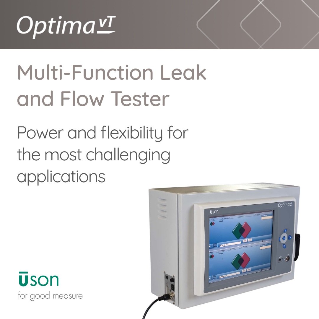
At the end of Test step, Optima vT looks for a specific back-pressure using its pressure sensor [PS]. If the measured back-pressure during the Test step is outside accept/reject setpoints entered into the test program, the Optima vT’s display shows why the part failed.
At the end of the test, any remaining pressure trapped in the part is vented to atmosphere through [V1] by opening [V2] only, and Optima vT is ready to make the next test.

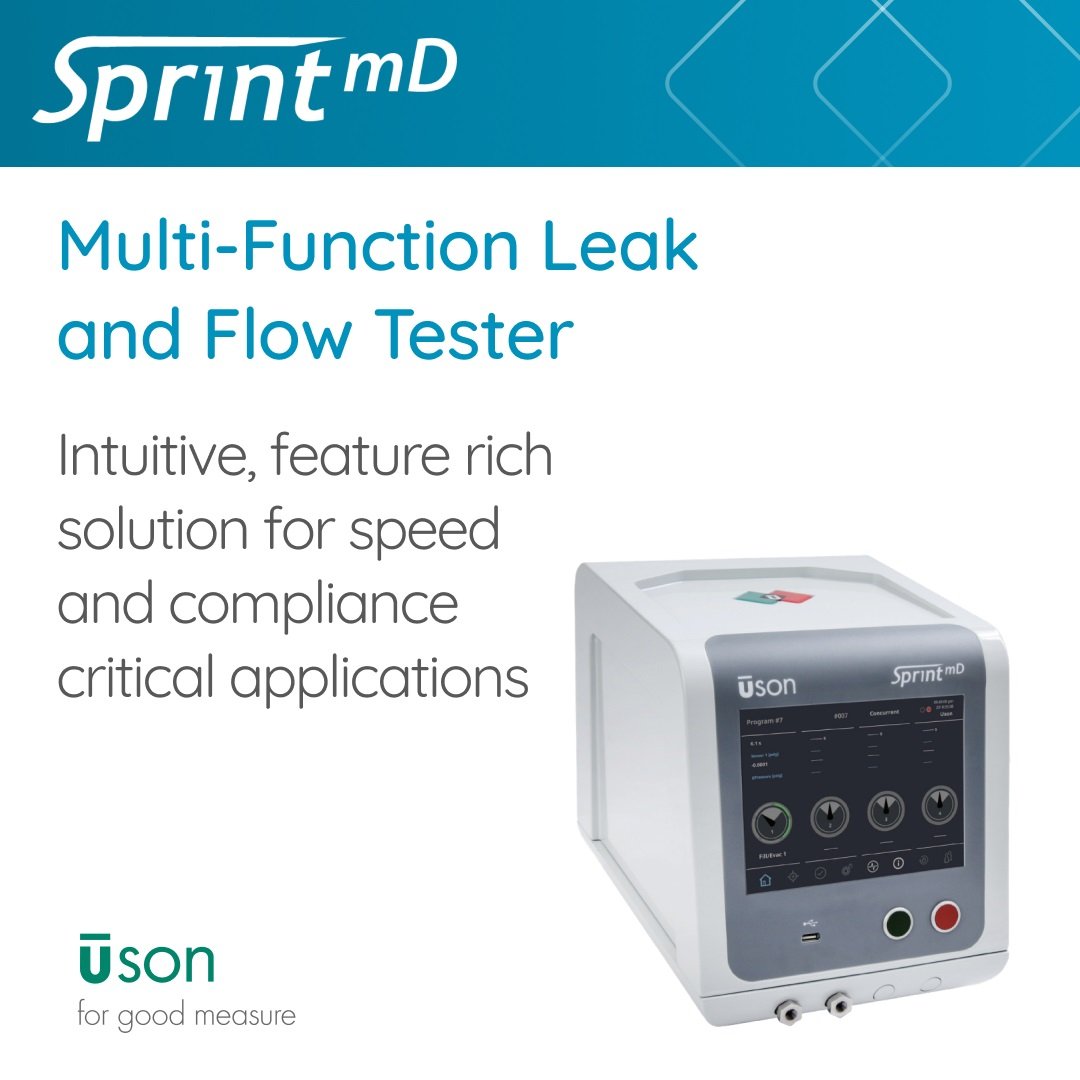
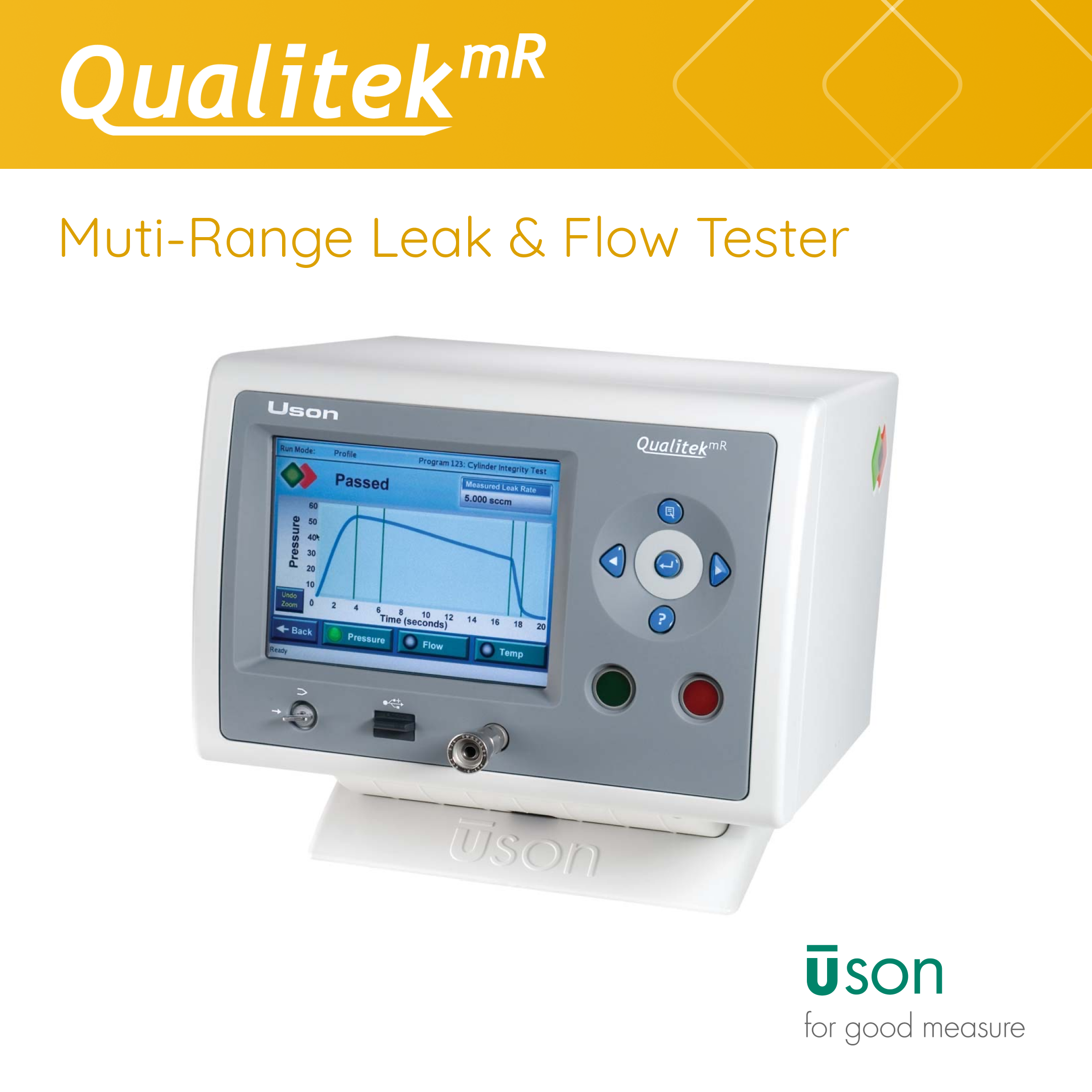
Testers Supporting Back-Pressure Flow Tests
The SaaS Sales & Marketing Acronym Bible
Industries
 English
 简体中文
简体中文
 Deutsch
 Español


.jpg)

