Vacuum Decay Leak Test

What is a Vacuum Decay Leak Test?
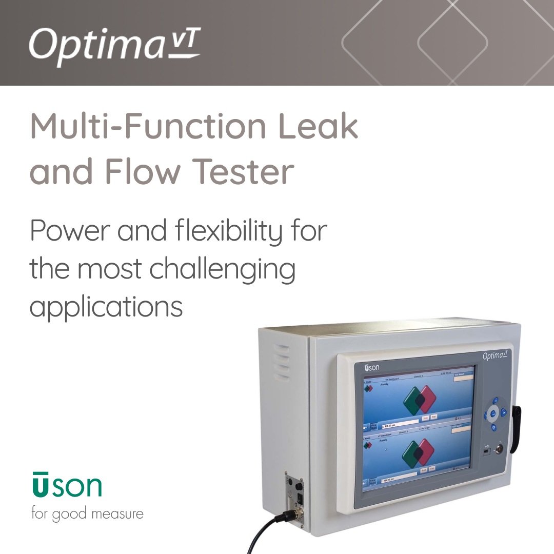
Vacuum Decay leak testing is used on a variety of products that can only be leak tested at negative pressure. The Optima vT can be used to leak test products, typically less than one liter at a fairly low vacuum, < 0.25 atm. Testing products greater than one liter can be achieved with high flow valves.
How Does a Vacuum Decay Leak Test Work?
The part to be tested [TP] is attached to the test port and the test is started.Positive pressure [+P] is applied to the vacuum generator [VG] through valve [V3]. The vacuum level is set by the pressure regulator [R1]. Vacuum can be supplied externally.
Negative pressure is supplied from [VG] to the test port by opening valves [V1] and [V2] during the Fill step.
At the end of the Fill step, negative pressure is then trapped inside the part as [V2] closes. After a slight delay, [V1] and [V3] close allowing the line between [V1] and [V2] to be vented to atmosphere through [V1]. This way, any leakage through [V2] will typically cause the tester to see this leakage and fail all tests.
Trapped negative pressure inside the test circuit is held through the Stabilize step and then measured by the tester’s vacuum sensor [VS] during the Test step.
If part exceeds the programmed leak tolerance (vacuum loss over time or quantified leak rate), the tester’s display indicates the reason for the test failure and displays the vacuum loss or leak rate in user defined units of measure.
At the end of Test step, negative pressure trapped in the part is vented to atmosphere through [V1] by opening [V2] only during the Vent step, and the tester is ready to make the next test.

Testers Supporting Vacuum Decay Leak Tests
Industries
 English
 简体中文
简体中文
 Deutsch
 Español

.jpg)
