 English
 简体中文
简体中文
 Deutsch
 Español

Leak Test Methods
Maintaining Leak Tight Seals with Autocouple Devices
Using Autocouple devices when leak testing smooth tubes and rough or irregular surfaces allows for maintaining a leak-tight seal.
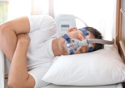 When it comes to breathing tubes, CPAP tubes, and any devices with similar air masks that support respiration, too much or too little air flow will impact the amount of oxygen the user gets, which can be dangerous. Air flow within these devices must fall within a very tightly specified flow range.
In leak testing, a typical range is that a device must not leak more than 5cc at 10 psi. However, in a breathing tube application, the specification needs to be much tighter — often 2cc at 100 psi. A leak tester must be flexible enough handle an extremely tight specification.
Additionally, applications like CPAP tubes must maintain a constant pressure, even in the presence of back pressure. Some devices can have vents that open in one direction and close in another. In this situation, a leak tester that can accommodate mass flow is required.
SOLUTION
Uson’s Optima vT leak tester, with its highly flexible platform and wide test range capabilities, is ideal for breathing tube applications.
The Optima vT has the capability to perform a flow test with the sensitivity down to 1 Pascal. It can also provide mass flow and back pressure testing. This means that it can meet the specification of a typical breathing tube application, which might look like:
Apply 40 Liters/minute to the inlet. The back pressure measured must be in the range of 6 to 9 cmH2O.
Mass Flow
The Optima vT tests mass flow using a mass flow computer (MFC). The MFC is used to generate and measure the specified mass flow. The analog output of the Optima vT is used to communicate the value of mass flow to be generated. The analog output of the MFC is connected to the Optima vT’s sensor input to display the actual mass flow reading during the test. The Optima vT’s closed loop control can also be used to fine tune the flow output to a very tight tolerance. Once the correct flow rate is established and settled the tester moves to the next step.
Back Pressure
The Optima vT utilizes a low pressure gauge transducer to measure pressure at the inlet of the part. It is important that the pressure sensing tap is as close to the part’s inlet as possible. If the pressure tap is not located near the part the system back pressure, it will be measured but the back pressure measurement will not be correctly recorded.
The velocity of the air versus the port size at the part may also need to be considered. If the velocity is too high, the pressure tap might be impacted by a Venturi effect. The Venturi effect is the reduction in gas pressure that results when a gas flows through a constricted section (or choke) of a pipe. This can be overcome by adding a plenum to the inlet seal head to the velocity.
It is also possible to have a specification that is written opposite of what is described above. For example:
Apply 7.5 cmH2O to inlet the flow in the range of 38 to 42 liters/min. In this case, it is necessary to use a pressure controller in conjunction with a mass flow meter.
SUMMARY
For very fine product flow inspection, Uson’s approach to breathing tube applications cannot be matched. With the Optima vT’s analog output and analog input measuring of the sensor’s output, the test station can be set for a variety of parts with different flow and back pressure tolerances. Along with all the other features included with the Optima vT, such as reading the bar code to select the correct program, customized data output, or Step Math, Uson can deliver an optimum test system to perform this type of test.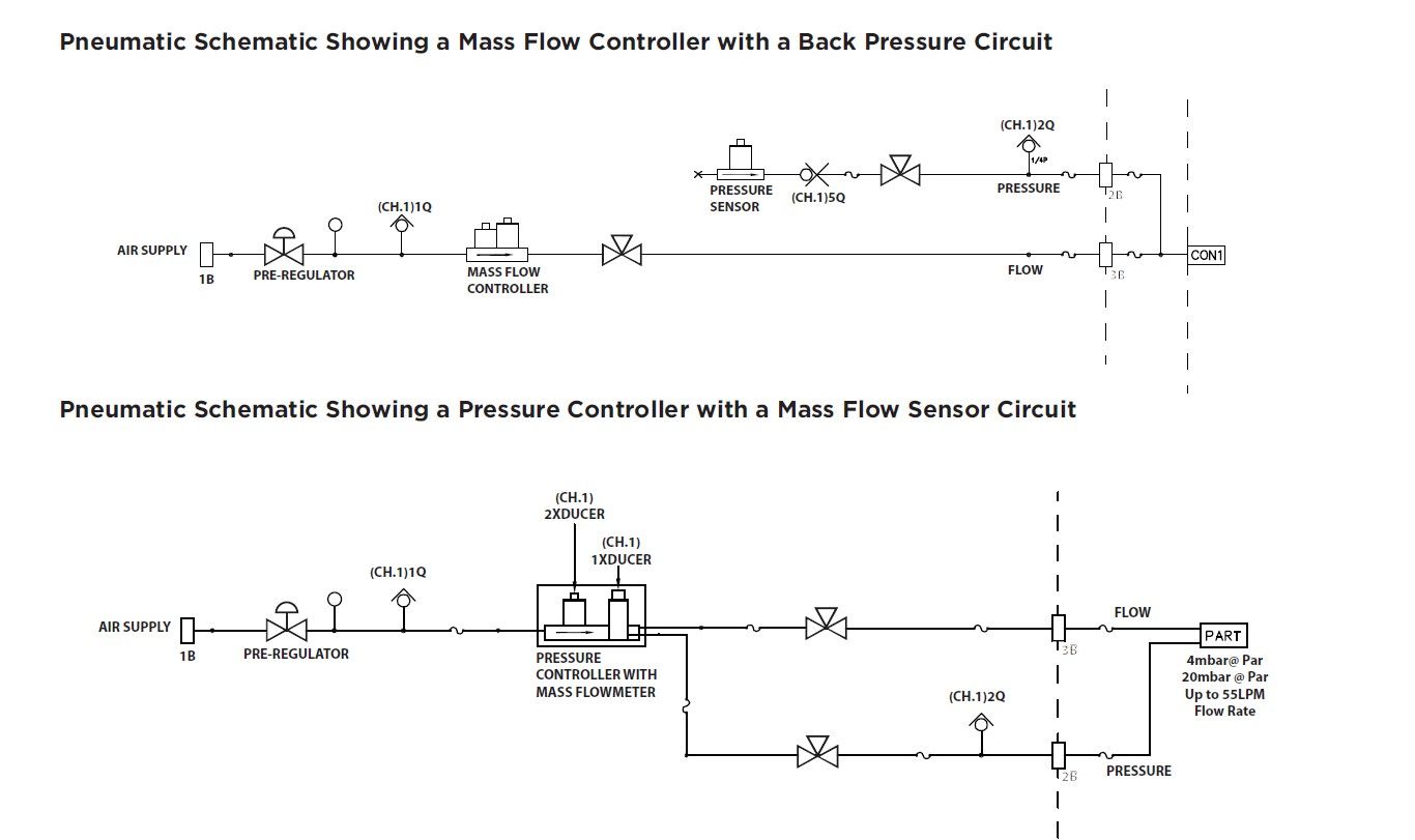

Using Autocouple devices when leak testing smooth tubes and rough or irregular surfaces allows for maintaining a leak-tight seal.
Uson offers medical device leak testing solutions for testing well plates using our Sprint mD leak and flow tester.
Uson offers equipment and solutions for effective catheter leak testing using our Sprint mD multi-function leak and flow tester.