In Part 2 of our series, we delve into the fundamental techniques of leak testing using air as the testing medium. While the straightforward method involves dunk testing, where compressed air is pushed into the test piece underwater, the approach has notable limitations. Commonly encountered in testing flexible packaging, dunk testing is subjective, relying on operator vigilance, and challenging to quantify. Moreover, it tends to be considered destructive. 
Non-subjective and Repeatable Leak Measurement Techniques
At Uson, our emphasis is on non-subjective and repeatable leak measurement techniques, instilling confidence in manufacturers. One such technique is the basic pressure decay leak test.
Pressure Decay Leak Test
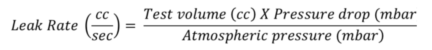
In a basic pressure decay test, the test piece is filled with air to a predetermined pressure. When the target pressure is reached the part is isolated from the air source and the air pressure is monitored with a pressure measuring device or transducer. If the air pressure drops more than an allowable amount over a certain time the part is determined to have failed the test. If we know the volume of the test piece and we know the pressure drop, we can calculate the leak rate.
The sequence of events in a pressure decay leak test is as follows:
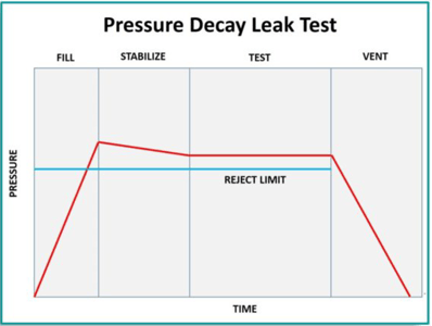
- Fill – the part is pressurized.
- Stabilize – the part is isolated from the air source and allowed to reach a stable condition to counter any adiabatic effects (see Is Temperature Change Affecting Your Leak Test Data?)
- Test – this is the step in which the air pressure is monitored for a pressure change.
- Vent – a vent valve in the pneumatic circuit I operated to allow the safe release of any pressure remaining in the part.
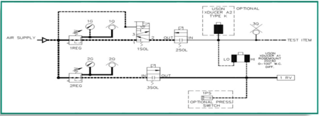
Differential Pressure Decay Test
A variation of the basic pressure decay test is the differential pressure decay test. This leak testing technique uses a differential pressure transducer placed in the pneumatic circuit between the pressurized test piece and a pressurized reference volume. The transducer monitors the pressure difference between the reference volume and the test part wherein changes of pressure in the test part cause a very thin flexible diaphragm in the transducer to move in one direction. The amount of movement is proportional to the change in pressure.
Pressure decay leak testing is useful for detecting small leaks quickly in relatively small volumes, up to one liter. Of the two methods, the differential decay method is faster and capable of detecting smaller leaks with greater accuracy. Both of the air decay tests calculate the leak rate indirectly.
Air Flow Measurement
Our next technique, flow measurement gives a direct reading in cc/minute. Flow rate measurement may take two forms – mass flow measurement and laminar flow measurement.
Laminar Flow Measurement
The principle of laminar flow measurement is simple. A measurement is taken in two places in the laminar flow tube. The difference in the pressure at both points is called the differential pressure and is proportional to the differential flow (the greater the flow the greater the pressure differential). The flowmeter which is comprised of a series of tubes may be placed after the test piece if it is designed to operate at a certain flow rate, for example, a valve. In this case, if there is a blockage the pressure measured at the flow meter will be lower than anticipated; if there is a large leak then the pressure will be higher than anticipated.
The flow meter may be placed after the test piece if the test piece is not supposed to leak or permit flow. If the differential pressure across the flow element is higher than expected, the part is leaking.
Mass Flow Measurement
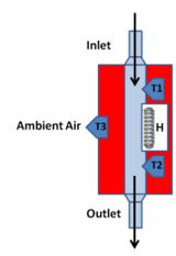 Electronic mass flow meters employ thermodynamic principles to measure the true mass flow rate, without the need for temperature or pressure compensation. The majority of instrumentation mass flow sensors are of the heated tube type. In these units, all or part of the gas flow passes through a precision sensing tube. A leak in the test component will result in a flow of air through the mass flow device. The mass flow sensor detection principle is based upon the transfer of heat in an air stream. Air flows across two temperature sensitive resistors, which are separated by a heated element. A sensor measures the difference in the air temperature recorded across the two resistors. A temperature difference results in an output voltage proportional to temperature. The amount of air that flows through the mass flow sensor is usually measured directly in cubic centimeters per minute.
Variations of Air Leak Testing Techniques
In addition to the popular air leak testing techniques described so far, there are other techniques which have limited but important applications.
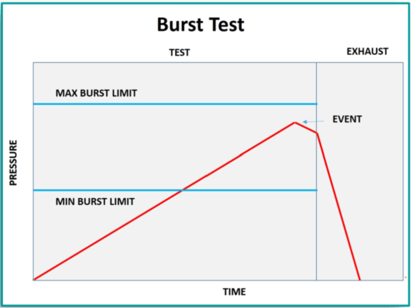
Burst Test
Certain products are engineered to endure specific pressures to prevent failure. This applies to various items, such as packaging for snack foods and pressure relief valves. In the event of excessive pressure, these products undergo a sudden release or "burst." Conversely, it is crucial that snack food packaging or pressure relief valves do not burst too readily. As a result, the burst test establishes two failure limits, with an acceptable range in between.
Creep Test
On occasions when an item is subjected to excessive pressurization, the resultant failure may not manifest as a dramatic burst but rather as a gradual expansion leading to eventual failure. Let's revisit the example of a snack food package. Each end of the package is heat-sealed. When pressurized and maintaining pressure, stress is exerted on the heat seal. If the seal is weak in a particular area, it will slowly separate, and if the weakness is pronounced enough, complete failure will occur. The creep test involves pressurizing the package and recording the time and pressure at which the failure transpires. In some instances, the test comprises multiple steps, incrementally ramping up the pressure each time.
Crack Test
The crack test is another variant of the burst test. It is designed to test a part, for example a valve, to see at which pressure it begins to open. Unlike the burst test, the “event” occurs unspectacularly. The failure criteria isa result that is below or above a predetermined pressure.
Versatile Leak Testing: Uson's Non-Subjective and Non-Destructive Approach
In summary, air pressure and flow measurement offer versatile leak testing techniques. Manufacturers can choose the method that best aligns with their specific applications. Uson's leak testing methods prioritize non-subjective and non-destructive approaches, with the exception of the burst test.
We've only just scratched the surface on the subject of leak testing. Stay tuned for upcoming posts in our The Beginners Guide to Leak Testing series:
- Part 1 – Why Leak Test?
- Part 3 – Beyond Air Pressure & Flow Measurement
- Part 4 – Leak Tester Features
- Part 5 – How To Buy a Leak Tester
Leak Testing Resources on Demand
Want more leak testing basics? You can find a plethora of resources right here at Uson.com. Check out our Blog and Resources section for educational articles, test method library, videos and more.
Uson can help!
If you're a beginner at leak testing (or know just enough to be dangerous) and need expert help identifying the right test method, process and leak tester for your application, the experts at Uson can help. Uson has helped thousands of product manufacturers around the world with their toughest application challenges for 60 years. We can help you too. Contact us today!
 English
 简体中文
简体中文
 Deutsch
 Español